CATALOGUE PRODUCT
AIM-T500
Insulation Monitor
Insulation-resistance monitoring for AC, DC and AC/DC hybrid IT systems within the manual's stated voltage range.
← All products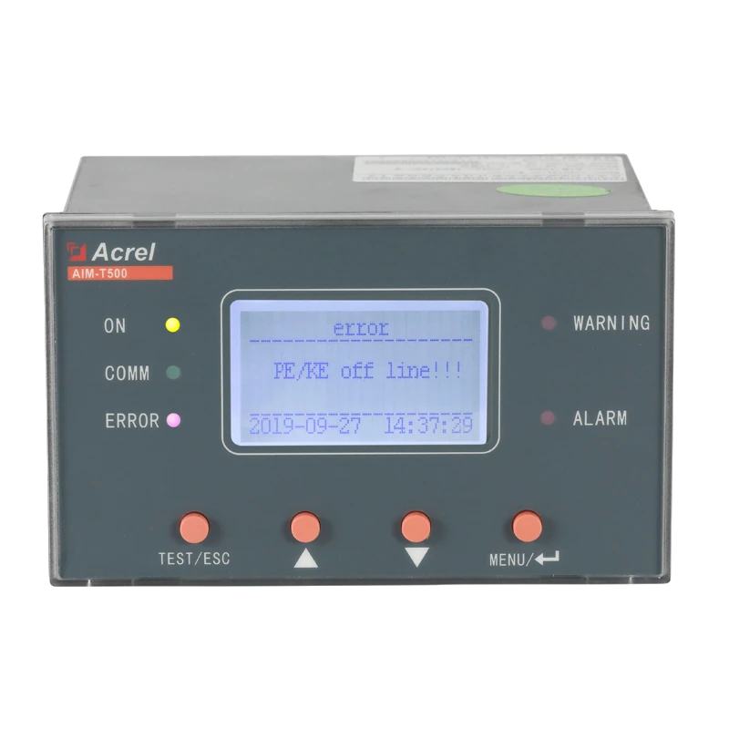 AIM-T500 front-view product photograph extracted from the supplied catalogue.
PRODUCT IDENTITY
Catalogue record
- Source catalogue
- SST固态变压器配套产品明细.xls
- Original product name
- 注入式绝缘监测装置
- Catalogue model
- AIM-T500
- Source location
- Sheet1, row 22
- Catalogue installation location
- 输出柜
- Image source
- Sheet1!F22 · xl/media/image33.png
Source notes
- AC/DC system-voltage ratings are distinct from the auxiliary-supply ratings.
- The <5 s response figure is specified at Ce =1 µF; the leakage-capacitance figure is <500 µF.
- The manual refers higher-voltage expansion to a separate ACPD manual; compatibility or higher limits are not inferred here.
- Listed reference standards are not described as certifications.
01Insulation resistance and leakage-capacitance monitoring
02PE/KE earth-connection monitoring
03Error, alarm and warning relay outputs
PRODUCT OVERVIEW
Product information
The AIM-T500 monitors insulation resistance and leakage capacitance to earth. It provides early warning, insulation alarms, PE/KE connection monitoring, device-error indication, event records, RS485 communication and panel mounting. Its system-voltage limits and response-time test capacitance are retained below.
Listed model
AIM-T500
TECHNICAL DETAILS
Specifications and their sources
- System voltage
- AC 0-690 V, 40-460 Hz; DC 0-800 VSource: AIM-T500 V1.7, PDF p.6, section 4 Technical Parameters
- Auxiliary supply / consumption
- AC 85-265 V, 50/60 Hz; DC 100-300 V; <8 WSource: AIM-T500 V1.7, PDF p.6, section 4 Technical Parameters
- Insulation-resistance measurement range
- 1 kΩ-10 MΩSource: AIM-T500 V1.7, PDF p.6, Measuring range Rf
- Response range
- 10 kΩ-10 MΩSource: AIM-T500 V1.7, PDF p.6, Response range Ran
- Resistance accuracy
- 1-10 kΩ: ±1 kΩ; 10 kΩ-10 MΩ: ±10%Source: AIM-T500 V1.7, PDF p.6, Resistance accuracy
- Leakage capacitance / response time
- Ce <500 µF; response <5 s at Ce =1 µFSource: AIM-T500 V1.7, PDF p.6, Leakage Capacitance and Response time
- Relay outputs
- Error, Alarm and Warning; 5 A at AC 250 V /DC 30 VSource: AIM-T500 V1.7, PDF p.6, Relay output
- Event records
- 20 records: fault type, fault value and fault timeSource: AIM-T500 V1.7, PDF p.6, SOE
- Communication / IP rating
- RS485 Modbus RTU /IP40Source: AIM-T500 V1.7, PDF p.7, Communication and IP Rating
- Operating environment
- -10 to +65 °C; RH <95%, non-condensing; altitude ≤2500 mSource: AIM-T500 V1.7, PDF p.7, Environment
- Mounting / cutout
- Panel mounting /74 ×127 mmSource: AIM-T500 V1.7, PDF pp.7-8, sections 6.1-6.2
CATALOGUE IMAGES
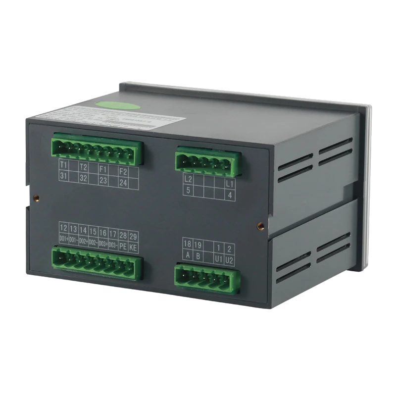
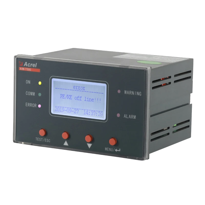
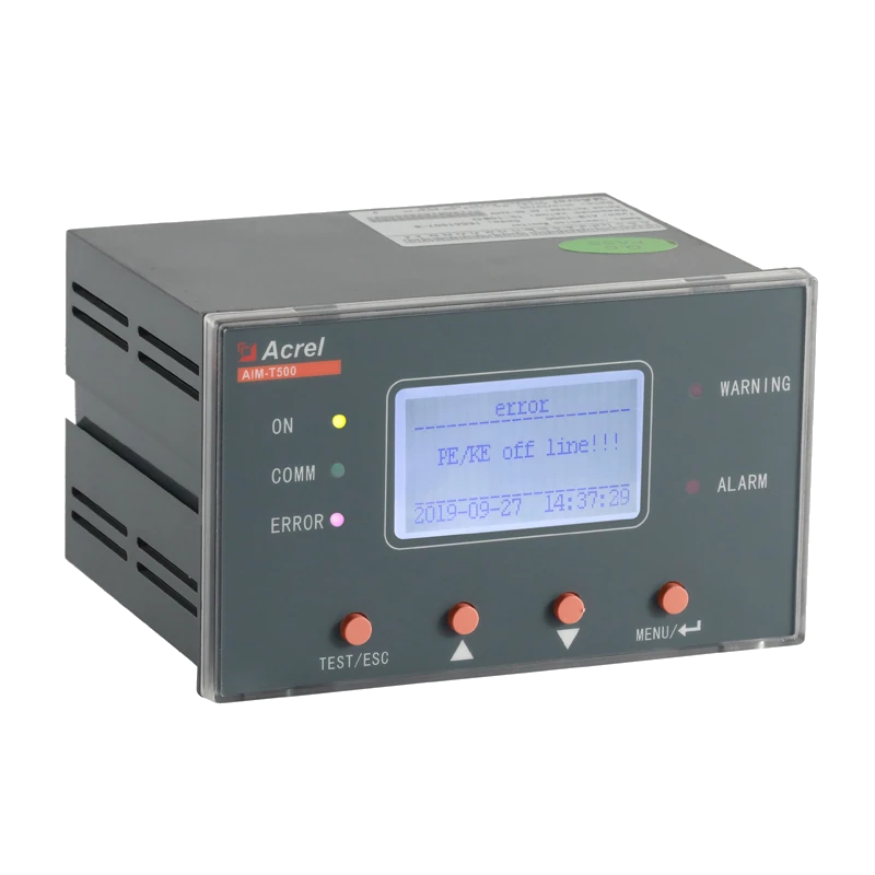
Additional views from the catalogue
CATALOGUE APPLICATION
Listed installation context
SOURCE DOCUMENTS
Original product manuals
AIM-T500 Insulation Monitor — User Manual
English · V1.7 · Relevant PDF pages 5, 6, 7, 8
Download original manual ↓PRODUCT QUESTIONS
Questions about this model
Which system voltages are listed for AIM-T500?
The technical table gives AC 0-690 V at 40-460 Hz and DC 0-800 V. It is not described here as an unrestricted high-voltage monitor.
Is the response time always below five seconds?
The manual states <5 s with system leakage capacitance Ce =1 µF. That condition is retained rather than presented as an unconditional response time.
Does the manual's standards list establish product certification?
The manual lists reference standards. This entry does not convert that list into a certification claim.
PROJECT SUPPORT
Evaluating AIM-T500?
Send the application, voltage, required functions, quantity and target delivery date.
Send project requirements →