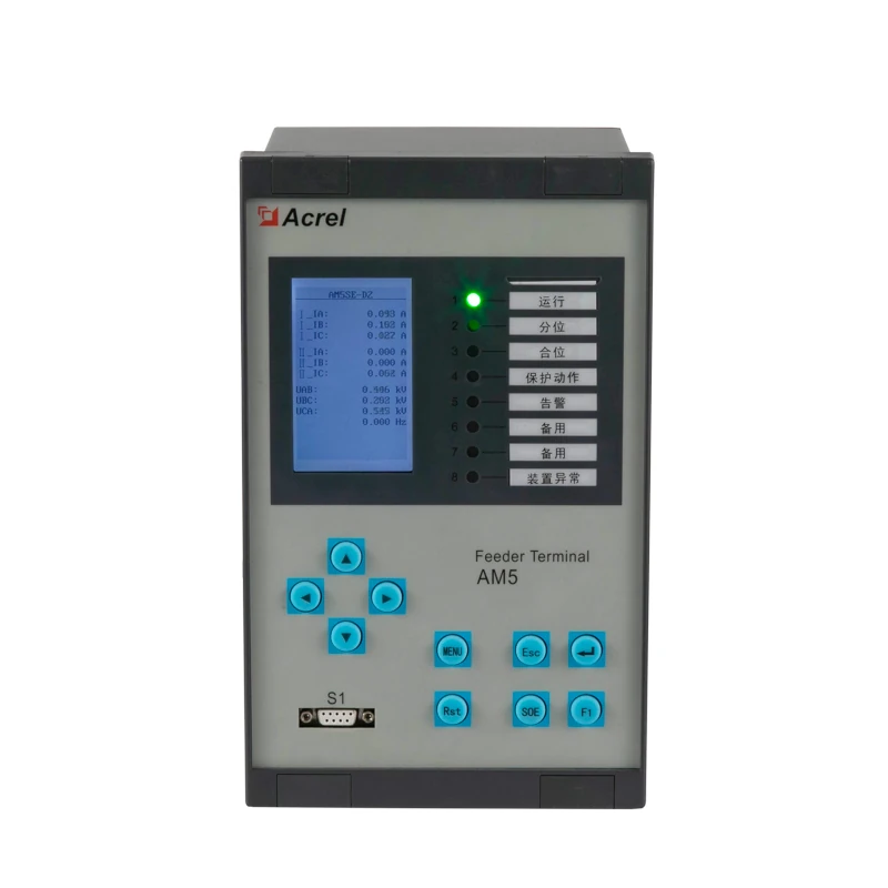
The practical starting point
Begin with the protected equipment and required functions, then select the matching AM5SE application column. The catalog lists AM5SE without a suffix, so it is a starting point for selection, not a complete ordering configuration. Check the electrical interfaces, terminal allocation and optional communications against that same selection before releasing an order.
- A relay family name does not confirm its protection functions. Resolve the application suffix before comparing hardware or price.
- Treat inputs, outputs and communications as separate selection decisions; a sufficient channel count does not prove a complete interface match.
- Ask for a configuration schedule and acceptance evidence that connect each project requirement to the selected relay and its drawings.
Start with the equipment and the protection duty
A useful specification begins with the circuit the relay will supervise. State whether the project concerns a feeder, transformer, motor, capacitor bank, busbar or another application covered by the selection guide. The AM5SE manual separates these duties into application-specific versions; selecting by the base name leaves the central engineering question unresolved.
Prepare a required-function list alongside the single-line diagram. For each function, identify the input information it needs and the intended trip, alarm or indication result. This gives the engineer a clear way to compare the application table with the project. Protection settings and coordination remain a separate engineering task; a matching function name does not establish the settings for a particular network.
- AM5SEApplication selection
- F / T / M / C / MD / D2 / D3 / TB / IS / FE / FA / B / K / UB / FD; functions vary by suffixAM5SE V1.7, PDF pp.6-8, section 1.2 Selection guide by application ↗
Review the catalog identity, application caveats and original manual on the AM5SE protection relay product page.
Background reading: IEC 60255-1:2022 — Common requirements for measuring relays and protection equipment · IEC ↗
Keep system quantities and relay inputs distinct
Record the installed CT secondary rating and confirm that the selected version actually has the required current inputs. The main technical table provides ratings for versions with current inputs; it should not be applied to a selection-table column in which those inputs are absent. If the project needs voltage measurements, also check that version's voltage-input arrangement in the original manual and proposed wiring drawing.
Auxiliary power is another independent item. Identify the control supply available at the relay, its nominal rating and the project's operating conditions. A system voltage on a single-line diagram does not identify the auxiliary supply. Keeping these entries separate makes it easier for the supplier and panel designer to detect a mismatch before wiring begins.
| Model / parameter | Documented value & source | What it means for selection |
|---|---|---|
| AM5SEProtection CT input — versions with current inputs | AC 1 A or AC 5 AAM5SE V1.7, PDF p.10, section 2.1 Phase CT Inputs (Protection Current) ↗ | Match the installed CT secondary to the selected relay version and confirm that the version provides the required current inputs. |
| AM5SEAuxiliary supply — listed main relay versions | AC/DC 110 V or AC/DC 220 V; rated voltage × (1 ±20%)AM5SE V1.7, PDF p.10, section 2.1 Rated Characteristics ↗ | Identify the available control supply separately from the primary system voltage, then confirm the selected ordering configuration. |
| AM5SERated frequency | 50 Hz or 60 HzAM5SE V1.7, PDF p.10, section 2.1 Frequency ↗ | Carry the project frequency through the selection sheet and acceptance documentation. |
Values retain the original manual conditions. On a narrow screen, scroll the table sideways.
Build an I/O schedule before accepting the channel count
List each required external signal by name, direction and destination. Examples for project planning include breaker status, an interlock indication, a trip command and an alarm output. These examples are requirements to review, not a statement that every function or electrical interface is included in every AM5SE version.
Then allocate the signals to the selected hardware and drawing. Keep any desired spare capacity visible. The manual's differing I/O entries make this step significant: copying the familiar main-variant count into every quotation can conceal a different hardware configuration. A channel total alone also does not establish the electrical suitability of a contact or input; review those details in the selected device documentation.
- AM5SEDigital inputs / outputs
- 20 /10 on the main listed variants; AM5SE-FD is listed as 12 /64AM5SE V1.7, PDF p.6, section 1.2 Digital rows ↗
| Project question | Evidence to request |
|---|---|
| Which circuit and protection functions? | Selected application suffix and a marked selection-table column |
| Which measurements are required? | Input ratings and a drawing matched to the installed instrument transformers |
| Which external signals are exchanged? | Signal-by-signal I/O allocation and terminal schedule |
| How will the relay connect to supervision? | Confirmed ports, protocol and the required option list |
This is a suggested project review record, not an additional AM5SE specification.
Specify the communication path and the information needed
State which supervisory system will receive the relay data and which interface it expects. The manual lists serial interfaces and protocols, while Ethernet entries are optional. An Ethernet requirement should therefore appear explicitly in the ordering review instead of being inferred from a family brochure or a photograph.
Also list the information the receiving system needs: measurements, status indications and relevant events, for example. Request the applicable protocol documentation and agree the point mapping before integration. A protocol name is a useful starting point, but it does not by itself confirm that the project's required points, data interpretation and communication configuration have been agreed.
- AM5SESerial interfaces in the selection guide
- 2 RS485 ports and 1 USB portAM5SE V1.7, PDF p.6, section 1.2 Rear port rows ↗
- AM5SESerial protocols
- Modbus Serial, IEC 60870-5-103 and IEC 60870-5-101 in the selection guideAM5SE V1.7, PDF p.6, section 1.2 Protocols rows ↗
- AM5SEOptional Ethernet
- 2 Ethernet ports; Ethernet-based protocols are marked optionalAM5SE V1.7, PDF p.6, section 1.2 Rear port and Protocols rows ↗
Plan how records will support operation
Fault and event records are useful only when the operating team knows how to retrieve and interpret them. The selection guide lists a fault recorder, circuit-breaker operation counts and sequence-of-event recording. Include the relevant record-access procedure and documentation in the handover request, rather than treating the presence of a recorder as the complete deliverable.
For acceptance, ask the supplier to demonstrate the agreed indications and record retrieval using an approved test procedure. Keep the tested configuration and resulting evidence with the relay documentation. This creates a traceable handover without assuming an undocumented storage capacity, timestamp accuracy or remote-access feature.
- AM5SERecords
- Fault recorder, circuit-breaker trip/close count and sequence-of-event recordAM5SE V1.7, PDF p.6, section 1.2 Logs and Records rows ↗
Example: reviewing a feeder-relay enquiry
Consider a hypothetical switchgear enquiry that says only “AM5SE, Ethernet required.” The first review question is the feeder's required protection duty. Next come the available current and voltage inputs, control supply, external signal list and supervisory interface. Those details let the supplier propose a specific suffix and option set for engineering review.
The useful result is a small evidence package: the proposed full designation, the relevant selection-table column, an I/O schedule, an interface drawing and a communication description. Any unanswered item stays visible in the quotation. This example describes a selection process; it does not nominate a suffix or settings for an unspecified feeder.
The order-release question
Can each required function and interface be traced to the proposed configuration? If an item is only described as an AM5SE family capability, obtain the selected-version confirmation before treating it as included.
Agree what acceptance will demonstrate
Separate document review from functional acceptance. Document review checks the supplied designation, options, drawings and manuals against the order. Functional acceptance follows the project's approved procedure to verify the required functions, external indications, outputs and communication mapping for that configuration.
The commissioning team should define safe test conditions and the extent of any complete-system checks. Retain the final settings record, drawing revisions and test evidence together. These are suggested handover controls, not a substitute for the relay manual or a protection study.
For a separate example of defining device and system acceptance boundaries, read the ARB4-A3 guide to relay action time and the complete trip path.
Information to prepare
Use these items to turn a product discussion into a reviewable project specification.
- Protected equipment, single-line diagram and required protection functions
- Proposed AM5SE application suffix and all ordering options
- CT secondary rating, required voltage inputs and system frequency
- Available auxiliary supply and selected relay supply rating
- I/O schedule, electrical interface checks and terminal drawing
- Supervisory interface, protocol, point mapping and Ethernet option if required
- Record retrieval, approved acceptance scope and handover documents
Common questions
Can I order from the XLS entry alone?
The XLS identifies AM5SE but leaves the application suffix unspecified. Use it to start an enquiry, then obtain the configuration needed for the protected equipment, interfaces and required functions.
Does choosing a model also determine protection settings?
No. Model selection establishes the available hardware and functions. The project engineer still needs to determine and approve settings and coordination for the actual network.
What should an Ethernet requirement include?
Identify the receiving system and requested communication function, then obtain confirmation of the optional ports, applicable protocol and point mapping for the proposed configuration.
What is the most useful quotation attachment?
A configuration schedule linked to the application table, interface drawing and I/O allocation makes the proposal reviewable. It shows which requirements are confirmed and which still need a project decision.
Check the original documentation
Product specifications above link to the relevant physical PDF pages. Project examples and checklists explain how to review a configuration; final settings and acceptance criteria belong in the approved project design.
- AM5SE Protection Relay — User Manual · V1.7 ↗English; Chinese/English setting tables
Explore the wider technical context
These official references provide background. Product ratings come from the selected-model manuals above; a reference does not establish product certification. Standards pages offer public summaries; full texts may require purchase.
- IEC 60255-1:2022 — Common requirements for measuring relays and protection equipment ↗IEC
Background on common requirements and testing for measuring relays and protection equipment.
Related technical guides
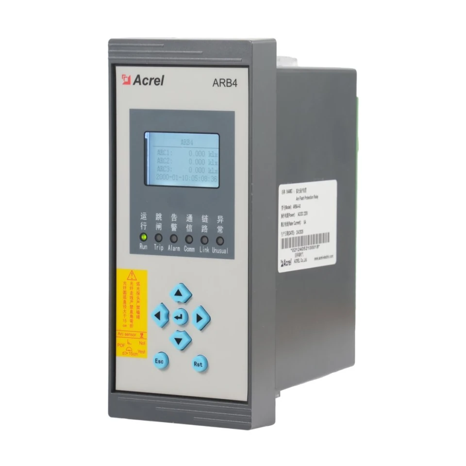
ARB4-A3 Arc Protection: From Relay Action Time to a Complete Scheme
Understand the timing boundary, sensing channels and trip-path decisions behind an ARB4-A3 scheme, with a practical review and acceptance framework.
Read guide →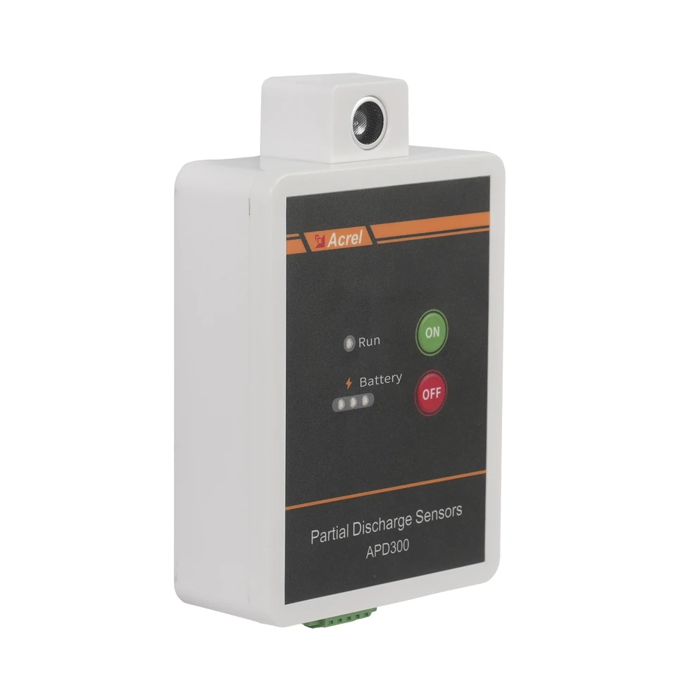
APD300-L Partial Discharge Monitoring: From Sensor Selection to Useful Trends
Build an APD300-L monitoring plan around the three sensing methods, the actual mounting position and a clear route from measurements to maintenance review.
Read guide →