CATALOGUE PRODUCT
ATE400
Passive Wireless Temperature Sensor
CT-powered wireless temperature sensor with alloy-strip fixing for electrical joints in high- and low-voltage switchgear.
← All products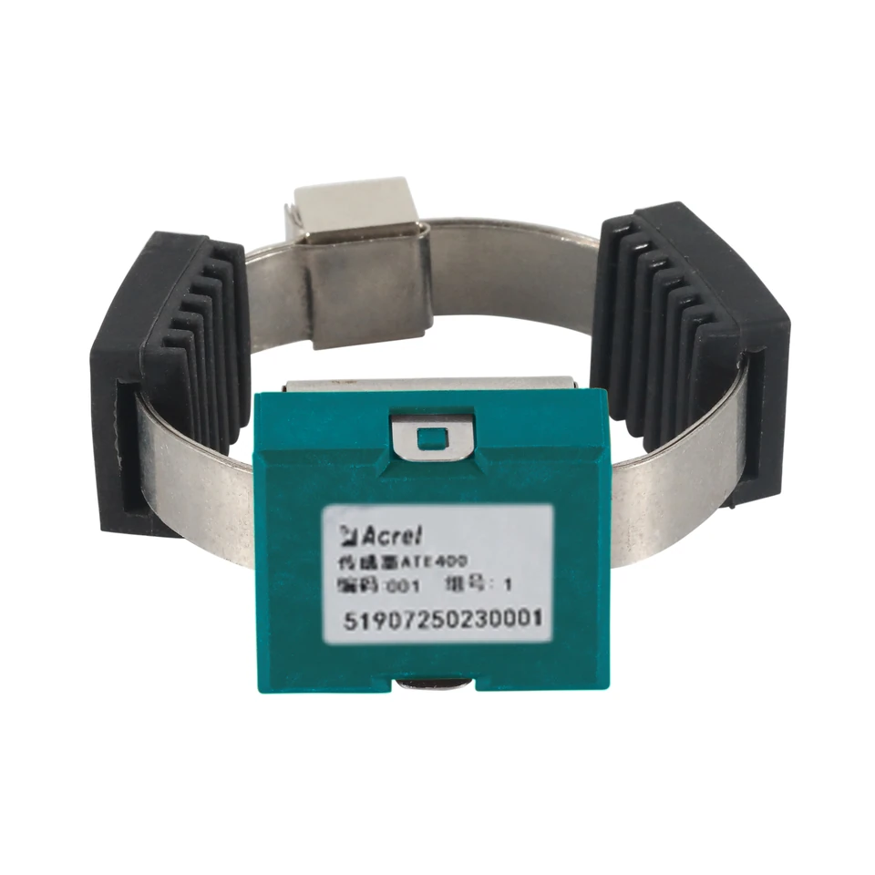 ATE400 product photograph extracted from the supplied catalogue.
PRODUCT IDENTITY
Catalogue record
- Source catalogue
- SST固态变压器配套产品明细.xls
- Original product name
- 无线测温传感器
- Catalogue model
- ATE400
- Source location
- Sheet1, rows 5, 10
- Catalogue installation location
- 中置柜 / 输入柜
- Image source
- Sheet1!E5 · xl/media/image8.jpeg
Source notes
- Only the ATE400 column is used for numerical specifications. ATE100P/200P IP68, ATE300P +300 °C and ATE210S/M starting-current values belong to other models.
- Communication distances are the manual's open-area figures. Receiver pairing and radio frequency must follow the corresponding model configuration.
01CT-induced power; starting current ≥5 A
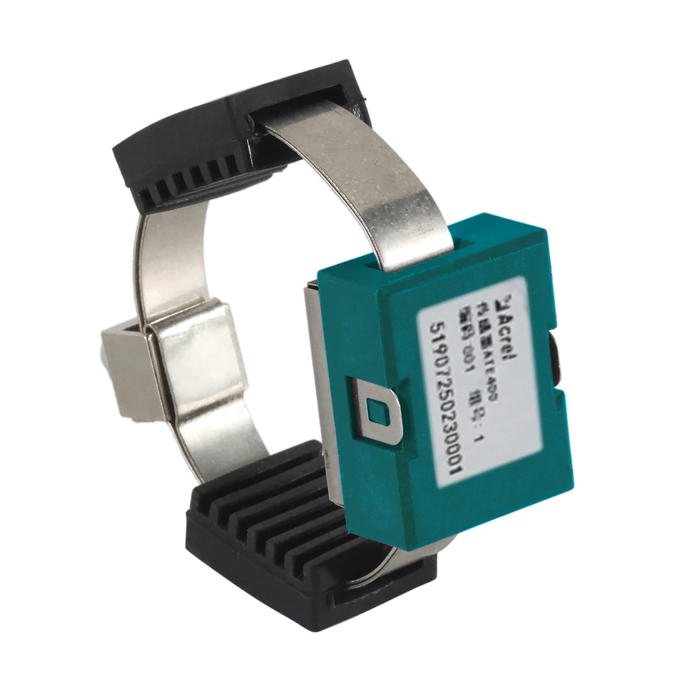
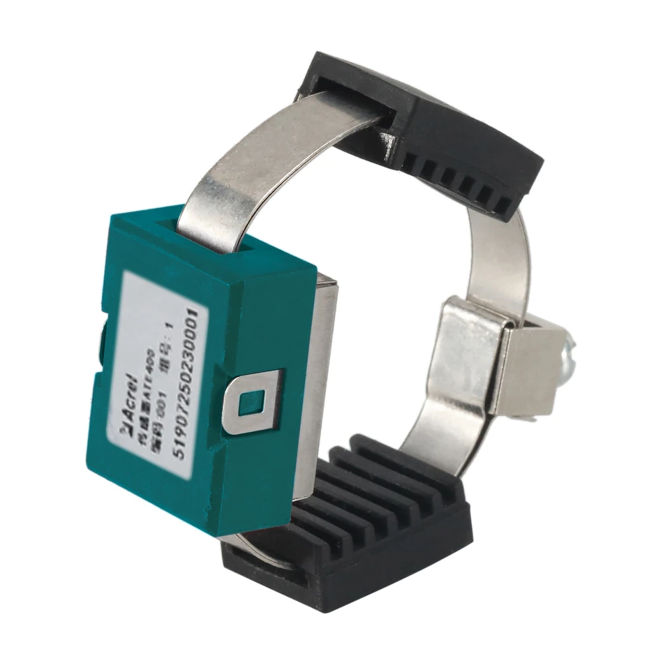
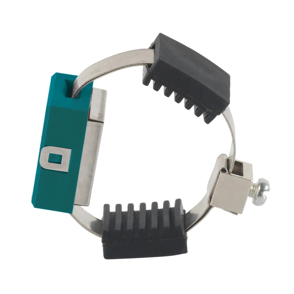
02Alloy-strip fixing
0315-second sampling and transmission
PRODUCT OVERVIEW
Product information
The ATE400 uses CT-induced power, with a starting current of at least 5 A. Its model-specific table gives a -50 to +125 °C measurement range, ±1 °C accuracy, 15-second sampling and transmission, and alloy-strip installation. Values for battery-powered and probe-output ATE models are not applied to ATE400.
Listed model
ATE400
TECHNICAL DETAILS
Specifications and their sources
- Power source
- CT-induced power; starting current ≥5 ASource: ATE V2.9, PDF pp.5-6, section 1.3 ATE400 table
- Maximum operating current
- ≤5000 ASource: ATE V2.9, PDF p.6, section 1.3 ATE400 table
- Measurement range
- -50 to +125 °CSource: ATE V2.9, PDF p.6, section 1.3 ATE400 table
- Accuracy
- ±1 °CSource: ATE V2.9, PDF p.6, section 1.3 ATE400 table
- Sampling / transmission
- 15 s /15 sSource: ATE V2.9, PDF p.5, section 1.3 ATE400 table
- Wireless frequency variants
- 470 MHz, 433 MHz or 868-923 MHz, as listed for ATE400Source: ATE V2.9, PDF p.5, section 1.3 ATE400 table
- Open-area communication distance
- 150 m at 470 MHz /868-923 MHz; 50 m at 433 MHzSource: ATE V2.9, PDF p.5, section 1.3 ATE400 table
- Installation
- Alloy-strip fixing; alloy-bottom sensor probeSource: ATE V2.9, PDF p.6, section 1.3 ATE400 table
- Application
- Electrical joints in high- or low-voltage switchgearSource: ATE V2.9, PDF p.6, section 1.3 ATE400 table
CATALOGUE IMAGES
Additional views from the catalogue
CATALOGUE APPLICATION
Listed installation context
SOURCE DOCUMENTS
Original product manuals
ATE Series Wireless Temperature Sensor — Installation Instruction
Chinese / English · V2.9 · Relevant PDF pages 4, 5, 6, 18, 19
Download original manual ↓PRODUCT QUESTIONS
Questions about this model
Does ATE400 need a battery?
The ATE400 table specifies CT-induced power with a starting current of at least 5 A.
Does the ATE400 range extend to +150 °C or +300 °C?
The ATE400 table specifies -50 to +125 °C. Higher ranges in the ATE manual belong to other models.
Does the ATE400 manual assign it IP68?
The ATE400 table does not state IP68. The IP68 entry is for ATE100P/ATE200P and is not transferred to ATE400.
PROJECT SUPPORT
Evaluating ATE400?
Send the application, voltage, required functions, quantity and target delivery date.
Send project requirements →