The practical starting point
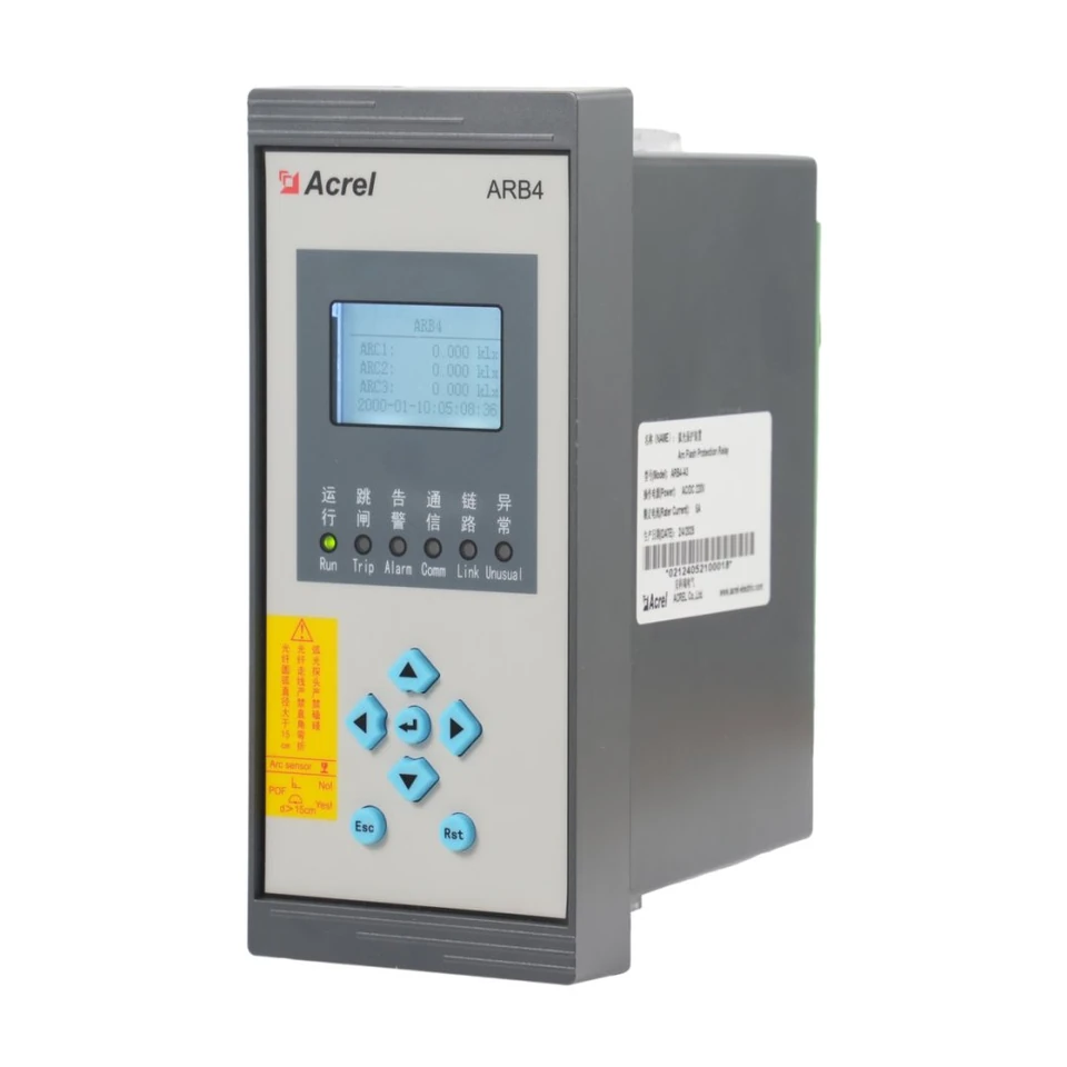
ARB4-A3 is the catalog's three-channel arc-protection relay. Its published action times describe the relay under stated input-threshold and output conditions. Evaluating a complete scheme also requires the selected detection criteria, sensor arrangement, trip path and circuit-breaker interruption behaviour; the relay figure alone does not establish total fault-clearing performance.
- Always state where a timing measurement begins and ends, together with the protection criterion and test conditions.
- Translate the cabinet arrangement into a reviewed sensor-to-channel and channel-to-output plan; channel count alone does not establish coverage.
- Confirm the exact sensor variant and complete trip path before making a system performance claim or accepting a component substitution.
Understand the decision the relay is being asked to make
The ARB4 manual describes arc-only, arc-and-current and arc-and-zero-sequence-voltage criteria. These names describe different combinations of information used by the protection scheme. An arc-only criterion acts on the relevant arc condition; a dual criterion also requires its associated electrical condition. The chosen criterion therefore affects both the required inputs and the acceptance procedure.
Begin by documenting which criterion is intended for each part of the scheme and why it fits the project's protection design. The available criteria are not an instruction to select one universally. The system designer must review the actual network, the required selectivity and the available measurement signals before approving the configuration.
- ARB4-A3Analogue inputs
- 4 current channels; 3 zero-sequence-voltage channelsARB4 v1.2, PDF p.16, section 1.4 Selection guide ↗
Read the action-time figures with their conditions
The manual gives separate arc-only and arc-and-current action times. Each figure retains a specified relationship between the applied signal and the action threshold, and identifies electromagnetic relay output. Removing those conditions turns a test result into a broader claim that the source does not support.
When reviewing a proposed test report, look for the chosen criterion, applied input conditions, measured output and timing endpoints. A result obtained under one criterion should not be presented as evidence for another without the relevant test. The published figures below are device action-time specifications, not a guaranteed time for every possible fault or a complete installation.
| Model / parameter | Documented value & source | What it means for selection |
|---|---|---|
| ARB4-A3Arc-only action time | ≤3.8 ms at twice the arc action threshold, using electromagnetic relay outputARB4 v1.2, PDF p.21, section 2.2 Basic mechanical design feature ↗ | Use this figure only with its stated arc-threshold and output conditions. Its endpoint is relay action, not complete fault-current interruption. |
| ARB4-A3Arc-and-current action time | ≤7.8 ms at twice the arc threshold and twice the current setting, using electromagnetic relay outputARB4 v1.2, PDF p.21, section 2.2 Basic mechanical design feature ↗ | Retain both input-threshold conditions when specifying or reviewing this criterion; evaluate the downstream trip path separately. |
Values retain the original manual conditions. On a narrow screen, scroll the table sideways.
A timing claim needs a boundary
Describe the signal condition that starts the measurement and the event that ends it. “Relay output operated” and “fault current interrupted” describe different endpoints.
Review the complete selected-model specification and source manual on the ARB4-A3 arc-protection relay page.
Follow the complete trip path
For a system-level review, follow the path from sensing through the protection decision to the trip circuit and the interrupting device. The ARB4 action-time entry covers a defined device behaviour. Any additional interface, trip-circuit operation and circuit-breaker interruption must be assessed using the corresponding equipment documentation and the project's test scope.
Do not add timing numbers unless their boundaries and conditions are compatible. A number measured from one input event cannot automatically be combined with another measured from a different event. The supplied ARB4 manual alone is insufficient to calculate a project-specific total clearing time or incident-energy result.
| Review item | What the evidence should identify |
|---|---|
| Detection and criterion | Selected logic, input signals and test stimulus conditions |
| Relay action | Timing endpoints, output type and applicable manual figure |
| Trip path | Interface arrangement, wiring and the device commanded to open |
| Complete clearing | Interrupting-device evidence and an agreed system measurement boundary |
This is a planning framework. It supplies no additional device delay or calculated clearing-time value.
Background reading: IEEE 1584-2018 — Guide for Performing Arc-Flash Hazard Calculations · IEEE ↗
Map channels to the actual cabinet arrangement
The A3 designation selects the channel count shown below. Treat that count as an interface capacity to allocate, rather than proof that a certain number of cabinets or compartments is fully covered. Sensor placement, viewing conditions, routing and the intended protection zones require review against the installation and the manufacturer's instructions.
A useful design drawing labels each proposed sensor, its location, the receiving channel and the intended output response. Review this alongside the primary arrangement so that a channel label has an unambiguous physical meaning. The manual's sensor and fiber-link self-inspection functions are also relevant to the operating team's handling of a monitoring-path problem; they do not remove the need to review the proposed layout.
- ARB4-A3Arc-sensor acquisition — A3
- 3 channelsARB4 v1.2, PDF p.16, section 1.4 Selection guide, ARB4-A3 column ↗
- ARB4-A3Digital I/O
- 8 active inputs; 5 normally-open outputsARB4 v1.2, PDF pp.11,16, interface resources and selection guide ↗
Confirm the sensor identity and auxiliary interfaces
The XLS lists an ARB-SO component separately, while the supplied ARB4 manual describes ARB-S sensors. The difference must be resolved with the supplier before treating the names as interchangeable. A grouped catalog row or system photograph is not enough to transfer one sensor's technical ratings or connection requirements to another designation.
Also review auxiliary supply and the chosen communication or time-synchronization interface. The manual makes RS485 and IRIG-B a selection between multiplexed interfaces. If a project asks for both, flag that request for configuration review rather than silently promising simultaneous operation. These interface decisions belong in the scheme documentation with the sensor selection.
- ARB4-A3Auxiliary-supply options
- AC/DC 220 V, AC/DC 110 V, DC 48 V or DC 24 V; rated voltage × (1 ±20%); ≤15 VAARB4 v1.2, PDF p.18, section 2.1.1 Power supply ↗
- ARB4-A3Communication / time synchronization
- One RS485 interface with Modbus or IEC 60870-5-103; RS485 and IRIG-B are multiplexed, select oneARB4 v1.2, PDF pp.16-17, selection guide and its note ↗
Example: turning a speed requirement into a reviewable scope
Consider a hypothetical enquiry requesting “fast arc protection for an input cabinet.” A useful response starts by identifying the proposed sensing locations, protection criterion and breaker to be tripped. The next questions concern the available electrical inputs, sensor designation, auxiliary supply and the customer's intended timing endpoint.
Suppose the customer expects proof of complete fault clearing. An ARB4 relay-output timing report would answer only part of that request. The review should identify the additional equipment evidence and system acceptance scope needed, instead of relabelling the relay result. No complete-system time can be assigned to this example from the supplied product documents.
Make acceptance evidence match the proposed scheme
Agree the acceptance plan before commissioning. It should connect the selected criterion, channel labels, output mapping, interface choices and timing requirements to specific evidence. Record the configuration used so that a test result can be understood later, including after a component or setting change.
Any functional or timing tests should follow an approved procedure under the commissioning team's controlled conditions. This article is a design-review guide, not an instruction to create an arc fault or test energized switchgear. A clear handover includes the final drawings, confirmed components, configuration record and the limits of the completed tests.
- Identify the sensing channel and expected response for each agreed test case.
- Record which detection criterion and output were evaluated.
- Keep relay timing evidence separate from evidence for the complete trip path.
- Document the agreed handling of sensor/fiber-link faults and communication indications.
For the related process of documenting protection functions, interfaces and handover evidence, see the AM5SE protection-relay selection guide.
Information to prepare
Use these items to turn a product discussion into a reviewable project specification.
- Cabinet arrangement, proposed sensing locations and intended protection zones
- ARB4-A3 designation and sensor-to-channel allocation
- Selected protection criterion and required electrical inputs
- Confirmed sensor designation, fiber components and connection documentation
- Trip destination, output allocation and complete interface drawing
- Auxiliary supply and RS485 or IRIG-B selection
- Timing boundaries, test conditions and the requested acceptance evidence
- Final configuration record, drawings and operating handover requirements
Common questions
Can the fastest relay figure be quoted as total clearing time?
No. It describes relay action under the stated criterion, input thresholds and output conditions. Complete clearing also requires evaluation of the actual trip path and interrupting device, with compatible measurement boundaries.
Does A3 mean that three cabinets are fully protected?
A3 identifies the listed arc-sensor acquisition channel count. Coverage depends on the approved sensing layout and protection design; the channel count alone does not establish cabinet coverage.
Can ARB-SO be substituted for the ARB-S described in the manual?
The supplied documents do not establish that substitution. Obtain the exact sensor documentation and confirmation of the proposed arrangement before assigning ARB-S ratings or compatibility to ARB-SO.
What makes an acceptance report useful?
It identifies the actual configuration, input conditions, channel and output mapping, timing endpoints and test result. It also states whether the evidence covers only the relay or a wider part of the installed scheme.
Check the original documentation
Product specifications above link to the relevant physical PDF pages. Project examples and checklists explain how to review a configuration; final settings and acceptance criteria belong in the approved project design.
- ARB4 Arc Flash Protection Relay — Operational Manual · v1.2 ↗Chinese / English / Russian
Explore the wider technical context
These official references provide background. Product ratings come from the selected-model manuals above; a reference does not establish product certification. Standards pages offer public summaries; full texts may require purchase.
- IEEE 1584-2018 — Guide for Performing Arc-Flash Hazard Calculations ↗IEEE
Background on the separate engineering study used to evaluate arc-flash exposure.
Related technical guides
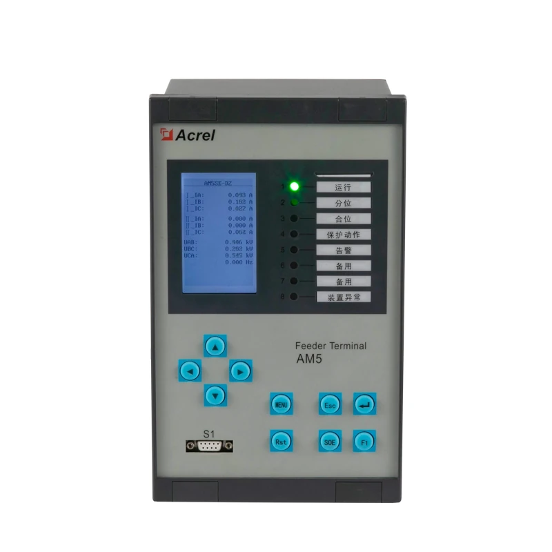
Selecting an AM5SE Protection Relay: From Application to Acceptance
Turn an AM5SE family reference into a reviewable specification: application suffix, electrical inputs, I/O allocation, communications and acceptance evidence.
Read guide →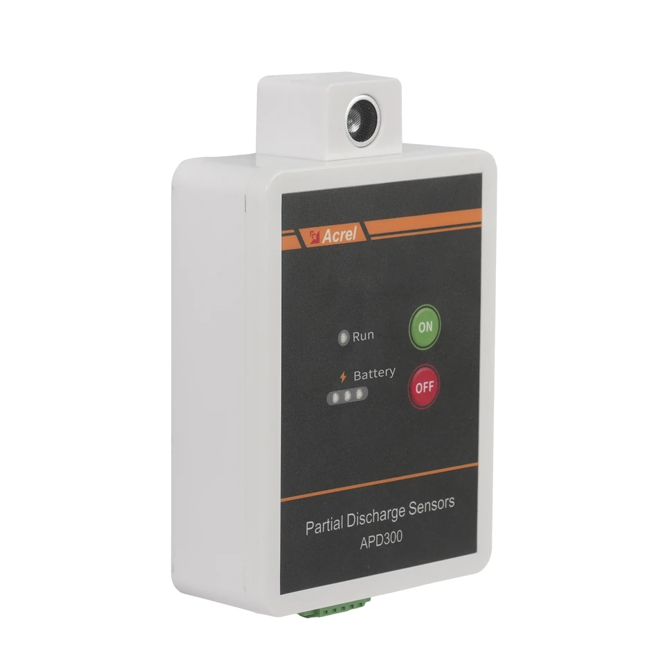
APD300-L Partial Discharge Monitoring: From Sensor Selection to Useful Trends
Build an APD300-L monitoring plan around the three sensing methods, the actual mounting position and a clear route from measurements to maintenance review.
Read guide →