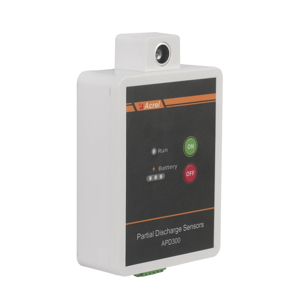
The practical starting point
For APD300-L, confirm the wired power and communication arrangement, preserve the separate AE, TEV and UHF measurements, and define how the team will review changes over time. The sensor supplies observations; the maintenance process gives those observations context.
- Select the wired APD300-L arrangement and plan its DC supply, RS485 route and host data collection together.
- Keep AE, TEV and UHF channels in their original units; a similar displayed number does not mean the same physical measurement.
- Record mounting position, operating conditions and data availability so that later changes can be investigated meaningfully.
Start with the insulation question the project must answer
The APD manual introduction describes partial discharge as a local discharge at an insulation defect that does not initially bridge the entire insulation. It explains how voids, impurities or sharp features can concentrate the electric field, and how continuing local damage can contribute to deterioration. This is the reason to look for developing insulation problems before a complete breakdown occurs. See the original manual, physical PDF page 5.
Define which compartment should be observed, who reviews a change, and what further assessment follows it. The supplied specifications do not establish remaining service life or a guaranteed fault location from a single reading.
To distinguish this task from resistance-to-earth monitoring in an IT system, see the AIM-T500 insulation-monitoring guide.
Design the wired arrangement as a complete data path
The catalog selects APD300-L. Plan its supply, communication and sampling entries together. Identify the supply and conversion module, the cable route to the receiving system, and who will integrate the Modbus data. Specify the host software separately.
Sampling cycle and the age of the value displayed by a host are different project questions. Polling, storage and display behavior also belong in the integration specification. During acceptance, check that the recorded measurement time and any communication interruption are understandable to the operator; a plausible-looking last value should not be mistaken for a current observation.
| Model / parameter | Documented value & source | What it means for selection |
|---|---|---|
| APD300-LPower supply | DC 12-36 V; standard DC/AC 220 V /110 V to DC 24 V conversion moduleAPD V2.2, PDF p.7, section 1.3 APD300-L column ↗ | Include the sensor supply and the specified conversion-module arrangement in the equipment schedule. |
| APD300-LCommunication | RS485, Modbus RTUAPD V2.2, PDF p.7, section 1.3 APD300-L column ↗ | Assign the communication route and host integration owner, and retain separate point names and source units. |
| APD300-LSampling cycle | 1 sAPD V2.2, PDF p.7, section 1.3 APD300-L column ↗ | Specify host polling, storage and display behavior separately; the sensor cycle alone does not determine dashboard update time. |
Values retain the original manual conditions. On a narrow screen, scroll the table sideways.
Check the exact L-variant specification and its source pages on the APD300-L wired partial-discharge sensor page.
Read AE, TEV and UHF as separate measurement channels
The three sensing methods give the review team different observations of the monitored equipment. The manual identifies ultrasonic AE, TEV and UHF measurements and assigns each its own range and frequency characteristics. Preserve those identities in the point list, dashboard and exported records. Combining all three into an unnamed 'PD level' discards information needed to interpret a change.
The units also matter: dBµV, dBmV and dBm are not interchangeable labels. A threshold or numerical comparison developed for one channel cannot simply be copied into another. Define any project alarm criteria with the responsible technical team and the actual installation context. The published measurement ranges are not, by themselves, recommended alarm limits.
- APD300-LUltrasonic AE
- 0-60 dBµV; resonant frequency 40 kHz ±1 kHzAPD V2.2, PDF p.8, PD monitoring sensors table, AE rows ↗
- APD300-LTEV
- 0-60 dBmV; signal bandwidth 3-100 MHzAPD V2.2, PDF p.8, PD monitoring sensors table, TEV rows ↗
- APD300-LUHF
- -70 to +10 dBm; 300-1500 MHz; average equivalent height ≥10 mmAPD V2.2, PDF p.8, PD monitoring sensors table, UHF rows ↗
| Record | Retain with the value | Review question |
|---|---|---|
| AE | Ultrasonic channel name and its source unit | Is this a persistent change from this position's previous observations? |
| TEV | TEV channel name and its source unit | Does the change remain when the operating context is considered? |
| UHF | UHF channel name and its source unit | What supporting observations should accompany this change? |
| Environmental readings | Noise, temperature and humidity as distinct points | What conditions coincided with the observation? |
These are proposed review questions, not a diagnostic algorithm or manufacturer alarm thresholds.
Background reading: IEC TS 62478:2016 — Electromagnetic and acoustic partial-discharge measurements · IEC ↗
Make the mounting position part of the specification
The APD300-L installation section places the magnetic sensor on the inner wall of the switchgear cable compartment. Plan the actual position on the cabinet drawing, with access and cable routing reviewed by the switchgear team. The external-door arrangement described for another APD variant is not an installation instruction for this model.
Retain a position identifier and installation photograph, and record later relocation or cabinet modification alongside the data. Coverage and sensor quantity need confirmation for the proposed compartments; the manual does not establish one universal allocation for every layout.
- APD300-LInstallation location — APD300-L
- Inner wall of the switchgear cable compartmentAPD V2.2, PDF pp.9-10, section 1.4.2 and Figure 1.4 ↗
- APD300-LDimensions / mounting
- 135 ×100 ×42 mm; magnetic mountingAPD V2.2, PDF p.8, Size and Installation rows ↗
- APD300-LOperating environment
- -40 to +85 °C; relative humidity ≤95% RHAPD V2.2, PDF p.8, Usage environment rows ↗
Build a reviewable baseline before relying on alerts
For project planning, define a baseline record containing the sensor identity, cabinet position, channel units, timestamps and relevant operating conditions. Include the available environmental observations without treating them as proof of a particular insulation defect. This gives the maintenance team something concrete to compare with a later change.
A useful review considers persistence, the behavior of the separate channels, changes in cabinet operation and whether data were missing. Escalation should lead to a documented technical assessment, not an automatic diagnosis based only on a large number. Agree who owns that assessment and where its conclusion will be recorded before the system is handed over.
- APD300-LEnvironmental measurements
- Noise 30-130 dB; temperature -40 to +85 °C; humidity 0-100% RHAPD V2.2, PDF p.8, PD monitoring sensors table, Environment rows ↗
Worked planning example: an input-cabinet monitoring point
Consider a proposed APD300-L position in an SST input cabinet. Start with the compartment drawing and the intended observation point. The cabinet team confirms mounting and wiring provisions; the controls team defines the RS485 connection and the host point names; the maintenance team specifies how a change will be reviewed. This is a planning example, not a tested customer installation or a coverage guarantee.
The acceptance record should connect those decisions. A reviewer should be able to trace a displayed UHF value to the correct cabinet, sensor and unit, distinguish it from TEV and AE, and identify a communication interruption. Separately, record whether the physical installation and supply arrangement match the approved drawing. That produces a maintainable monitoring point rather than an isolated display of numbers.
A useful acceptance question
Can another engineer follow one observation from its cabinet position through the host record to the agreed maintenance review process? If a link is missing, resolve it before calling the monitoring arrangement complete.
Hand over the configuration as well as the hardware
Keep the mounting drawing, device identities, communication settings, host point mapping and acceptance record together. Document approval of alert criteria and treatment of missing data as integrator deliverables.
Use the original APD300-L sections for installation and communication. Retain the L suffix throughout drawings and software records to avoid importing wireless accessories or timing assumptions from APD300-W or APD300-WP.
Information to prepare
Use these items to turn a product discussion into a reviewable project specification.
- Exact APD300-L identity and the cabinets or compartments to be observed.
- Approved mounting positions, access provisions and cable routes.
- DC supply and conversion-module arrangement.
- RS485 integration owner, device identities and host point mapping.
- Separate AE, TEV, UHF and environmental records with original units.
- Timestamp, data-retention and communication-loss requirements for the host.
- Baseline context, agreed alert review process and responsible personnel.
- Installation, integration and handover acceptance evidence.
Common questions
Can I use the same alarm number for all three sensing methods?
No common threshold is established by the supplied specifications. AE, TEV and UHF use distinct measurements and units. Project criteria need their own technical basis and approval.
Does a one-second sampling cycle guarantee a one-second dashboard update?
No. The sensor's sampling specification does not describe the host polling, storage or display cycle. Confirm the complete data path during integration.
Can this guide determine the sensor quantity for my switchgear?
It identifies the documented model and mounting location. It does not establish universal coverage or quantity for different compartment layouts; those require a project-specific review.
Does the environmental measurement range replace the operating limit?
No. A measured quantity's range and the sensor's permitted operating environment are separate entries. Check the operating-environment specification when assessing the installation.
Check the original documentation
Product specifications above link to the relevant physical PDF pages. Project examples and checklists explain how to review a configuration; final settings and acceptance criteria belong in the approved project design.
- APD Series Partial Discharge Detector — Operation Manual · V2.2 ↗Chinese / English
Explore the wider technical context
These official references provide background. Product ratings come from the selected-model manuals above; a reference does not establish product certification. Standards pages offer public summaries; full texts may require purchase.
- IEC TS 62478:2016 — Electromagnetic and acoustic partial-discharge measurements ↗IEC
Scope of electromagnetic and acoustic partial-discharge measurements, including sensor sensitivity and measurement-system checks.
Related technical guides
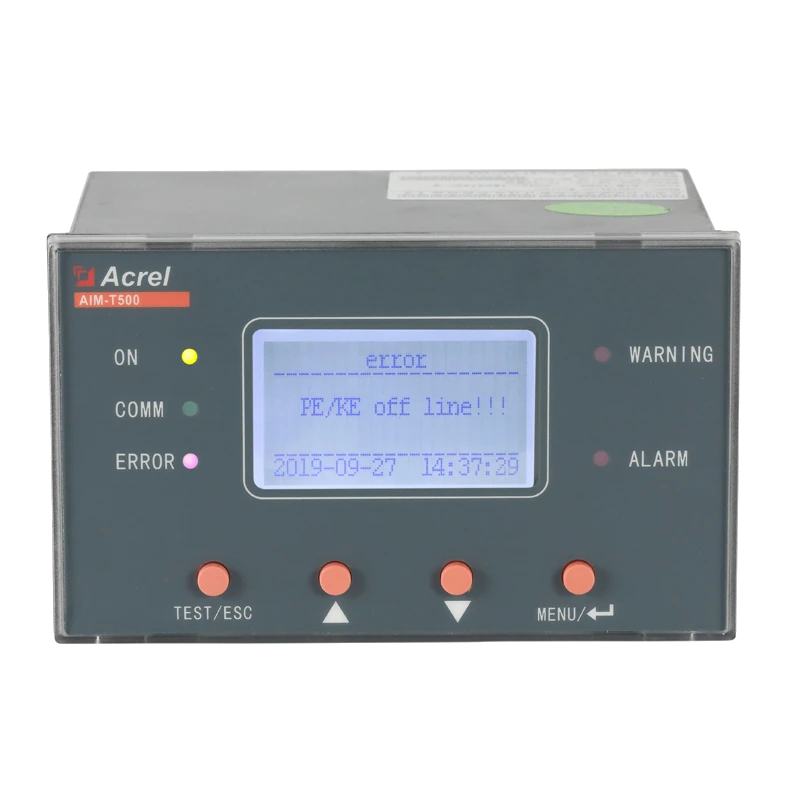
AIM-T500 for IT Systems: Resistance, Capacitance and an Actionable Alarm Plan
Understand what AIM-T500 monitors, why system capacitance matters, and how to specify voltage limits, warning outputs and acceptance evidence for an IT-system project.
Read guide →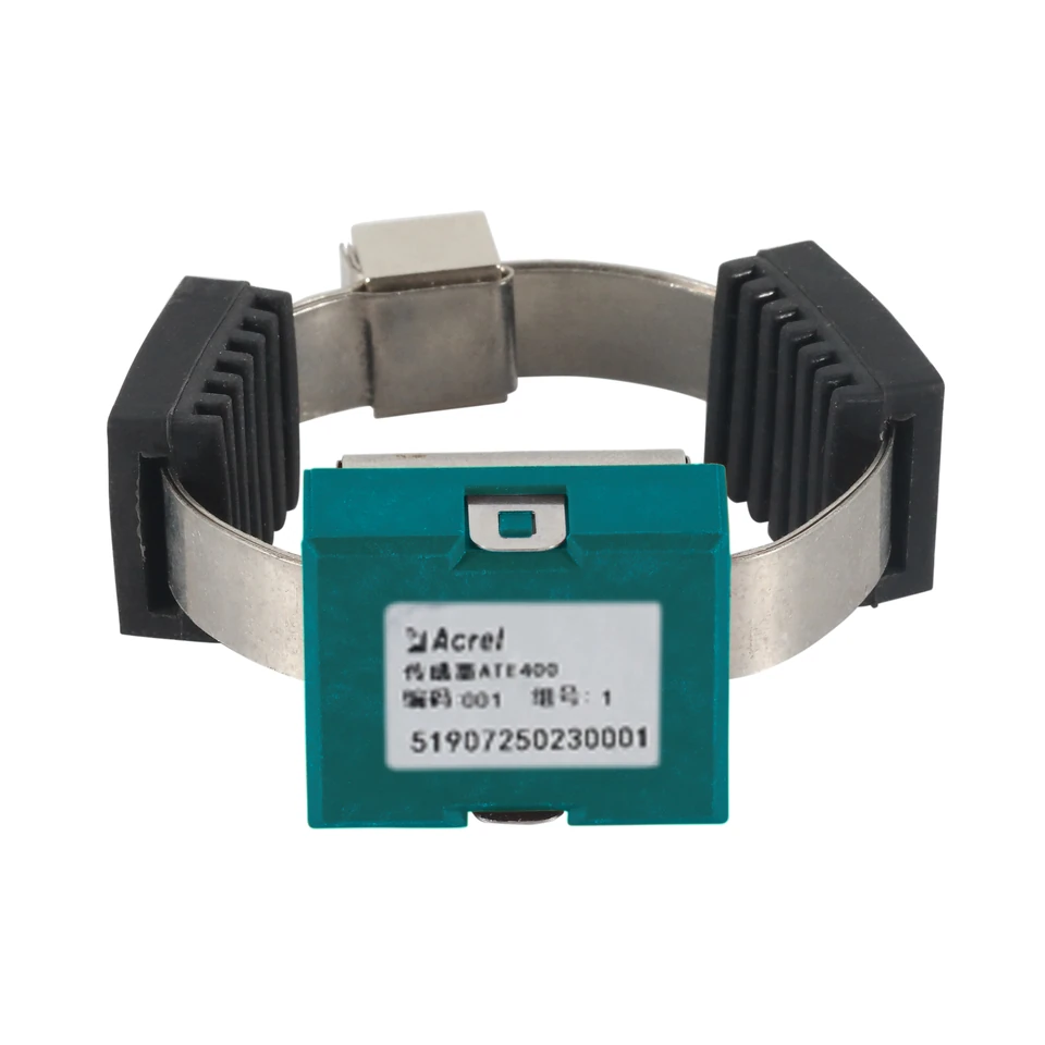
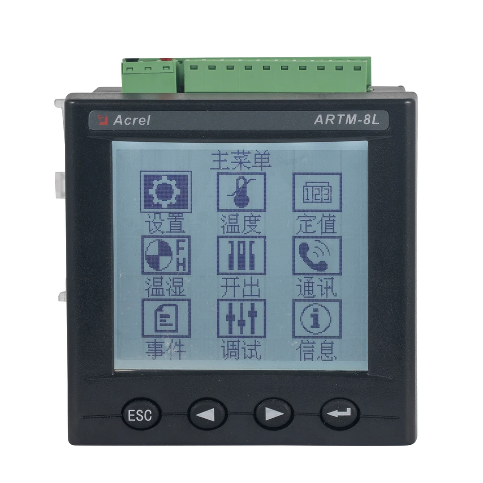
Wireless or Wired Temperature Monitoring? ATE400 and ARTM-8L Selection Guide
Compare the complete measurement paths, from sensor power and probe selection to receiver capacity, alarm outputs and acceptance checks.
Read guide →