The practical starting point
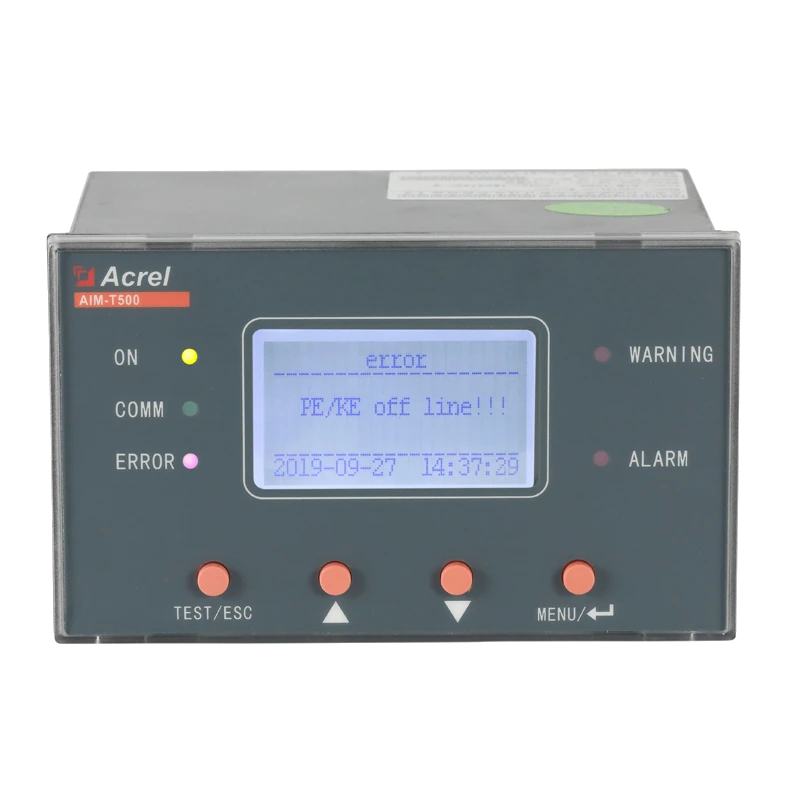
AIM-T500 monitors insulation resistance to earth in AC, DC and hybrid IT systems. Distinguish auxiliary power from the monitored-system rating, keep the capacitance condition attached to response time, and define the operator response to Warning, Alarm and Error indications.
- Confirm the actual earthing arrangement and monitored electrical section before selecting an insulation monitor.
- Review system voltage, auxiliary supply, resistance ranges and system capacitance as separate requirements.
- Plan the alarm response and monitoring-health indication along with the instrument and communication interface.
Why an IT system needs a different insulation question
Here, IT refers to the electrical earthing arrangement, not information technology. The AIM-T500 manual introduction discusses unearthed AC and DC systems used where continuity of supply matters. It explains that earth-fault current can be too low for ordinary switching devices to detect and trip, making insulation resistance to earth a separate quantity to monitor. See physical PDF page 5.
Define how personnel will respond to insulation deterioration. A monitor does not establish permission to continue operating after any fault; that response belongs in the installation's approved protection and maintenance arrangements.
Background reading: IEC 61557-8:2014 — Insulation monitoring devices for IT systems · IEC ↗
Understand resistance and capacitance together
The manual describes an injected low-frequency AC measuring signal. Its frequency is adjusted according to measured system-to-earth capacitance to determine insulation resistance while reducing the capacitance's influence on the measurement. That description explains why the product reports both insulation resistance and leakage capacitance, rather than treating capacitance as an unrelated accessory value.
A resistance alarm concerns the connected monitored section; it does not identify a faulty branch. Plan the follow-up investigation separately and record configuration changes so the team knows which electrical arrangement a reading represents.
Keep the monitored boundary explicit
Mark the electrical section on the single-line diagram and state which switching configurations are included. An unambiguous boundary makes an insulation trend and an alarm record more useful to the team investigating it.
For a separate monitoring method based on local-discharge observations, read the APD300-L partial-discharge monitoring guide.
Separate four ratings that answer different questions
The voltage of the system being monitored is not the supply that powers the instrument. Both must fit their respective entries. Also separate the resistance measurement range from the response-setting range: the ability to display a resistance does not mean every displayed value is an available alarm setting.
Give each requirement its own row on the selection sheet. Include AC frequency explicitly instead of assuming the monitored system has the same frequency as the instrument supply.
- AIM-T500System voltage
- AC 0-690 V, 40-460 Hz; DC 0-800 VAIM-T500 V1.7, PDF p.6, section 4 Technical Parameters ↗
- AIM-T500Auxiliary supply / consumption
- AC 85-265 V, 50/60 Hz; DC 100-300 V; <8 WAIM-T500 V1.7, PDF p.6, section 4 Technical Parameters ↗
- AIM-T500Insulation-resistance measurement range
- 1 kΩ-10 MΩAIM-T500 V1.7, PDF p.6, Measuring range Rf ↗
- AIM-T500Response range
- 10 kΩ-10 MΩAIM-T500 V1.7, PDF p.6, Response range Ran ↗
| Requirement | What it describes | Information to supply |
|---|---|---|
| System rating | The electrical section being monitored | AC, DC or hybrid arrangement, voltage and relevant frequency |
| Auxiliary power | The source powering AIM-T500 | Available instrument supply and its project limits |
| Measurement range | Resistance values the instrument measures | Expected insulation values and required observation range |
| Response range | Available resistance response settings | Proposed warning/alarm settings and their engineering basis |
Find the complete selected-model limits and original manual on the AIM-T500 insulation-monitoring device page.
Treat the response-time condition as part of the requirement
The manual gives a leakage-capacitance limit and a response-time figure at a specified capacitance. Those are separate statements. The response value cannot be extended unchanged across the whole capacitance range. If response speed matters to the process, state the expected capacitance and operating arrangement when requesting confirmation.
Record capacitance and other test conditions alongside the measured response. If the installation changes materially, review whether previous acceptance evidence still represents the monitored system.
| Model / parameter | Documented value & source | What it means for selection |
|---|---|---|
| AIM-T500Leakage capacitance / response time | Ce <500 µF; response <5 s at Ce =1 µFAIM-T500 V1.7, PDF p.6, Leakage Capacitance and Response time ↗ | Record the actual system-to-earth capacitance with any response-time requirement. Do not extend the stated test result unconditionally across the complete capacitance range. |
| AIM-T500Resistance accuracy | 1-10 kΩ: ±1 kΩ; 10 kΩ-10 MΩ: ±10%AIM-T500 V1.7, PDF p.6, Resistance accuracy ↗ | Retain the applicable measurement conditions when reviewing acceptance results and the required observation range. |
Values retain the original manual conditions. On a narrow screen, scroll the table sideways.
Give Warning, Alarm and Error different meanings in the project
AIM-T500 provides outputs identified as Warning, Alarm and Error. Its manual also describes PE/KE connection monitoring. Preserve those distinctions on the host display and in the operating procedure: an insulation warning and a problem with the monitoring arrangement should not appear as the same anonymous alarm.
Define who receives each indication and how investigation is recorded. The local event record is limited, so specify any longer host history separately. Retention, notifications and operator workflow are integration requirements beyond the RS485 interface.
- AIM-T500Relay outputs
- Error, Alarm and Warning; 5 A at AC 250 V /DC 30 VAIM-T500 V1.7, PDF p.6, Relay output ↗
- AIM-T500Event records
- 20 records: fault type, fault value and fault timeAIM-T500 V1.7, PDF p.6, SOE ↗
- AIM-T500Communication / IP rating
- RS485 Modbus RTU /IP40AIM-T500 V1.7, PDF p.7, Communication and IP Rating ↗
Check switching topology and the full installation arrangement
A bus tie can change the electrical section under observation. The manual describes an interlock function for interconnected bus sections, so a project with multiple sections needs a topology review as well as a device count. Define which monitor is intended to operate in each switching state and have the detailed arrangement checked against the original wiring instructions.
Also review the panel location, environmental limits, wiring space and access for maintenance. Higher-voltage expansion is referred to a separate ACPD document in the AIM-T500 manual. That separate manual is not included in this entry; this guide therefore does not extend the stated system-voltage limits or assert an unverified coupling configuration.
- AIM-T500Operating environment
- -10 to +65 °C; RH <95%, non-condensing; altitude ≤2500 mAIM-T500 V1.7, PDF p.7, Environment ↗
- AIM-T500Mounting / cutout
- Panel mounting /74 ×127 mmAIM-T500 V1.7, PDF pp.7-8, sections 6.1-6.2 ↗
Worked planning example: an unearthed DC section
For a proposed unearthed DC section within the documented voltage limit, begin with its single-line diagram, voltage and auxiliary supply. Add the expected system-to-earth capacitance, normal switching states and the required warning response. The engineering team then checks the selected instrument against those inputs and approves the response settings and operating procedure. This example is a planning sequence, not a commissioned installation.
An effective acceptance record covers more than a resistance display. It should show the agreed indications at the instrument and host, the distinction between insulation alarms and monitor errors, and the relevant test conditions. Use the manufacturer's documented test procedure through qualified personnel; the manual places specific conditions on self-test connections, so ad hoc fault simulation is not an acceptance method supplied by this guide.
- Match the installed device, monitored boundary and supply to the approved selection sheet.
- Record approved settings and how Warning, Alarm and Error are represented to operators.
- Retain test conditions and results, including the capacitance context for any response-time evidence.
- Hand over the drawings, communication mapping, operating response and maintenance responsibilities together.
Information to prepare
Use these items to turn a product discussion into a reviewable project specification.
- IT earthing arrangement and the monitored section on the single-line diagram.
- AC, DC or hybrid system voltage and relevant AC frequency.
- Available auxiliary supply, separate from the monitored-system rating.
- Expected resistance, leakage capacitance and required response conditions.
- Proposed Warning and Alarm settings with their project engineering basis.
- Error indication, PE/KE connection monitoring and operator response requirements.
- Bus-tie operating states, RS485 integration and event-history requirements.
- Installation review, documented acceptance procedure and handover records.
Common questions
Does an insulation alarm locate the faulty outgoing circuit?
The documented function measures insulation resistance to earth for the connected system. It does not establish branch-level fault location. The project needs a separate investigation process.
Can I choose alarm settings from the measurement-range limits?
The manual lists a distinct response range. Even within that range, selecting a setting requires the project's operating requirements and engineering review; the range endpoints are not recommended settings.
Does the response figure apply at the maximum permitted capacitance?
The published response figure is tied to its stated test capacitance. It is not an unconditional guarantee at every capacitance within the product limit.
Does a monitoring alarm itself decide whether operation can continue?
No. The instrument supplies indications and outputs. The required operational action must be defined by the installation's approved protection, operating and maintenance arrangements.
Check the original documentation
Product specifications above link to the relevant physical PDF pages. Project examples and checklists explain how to review a configuration; final settings and acceptance criteria belong in the approved project design.
Explore the wider technical context
These official references provide background. Product ratings come from the selected-model manuals above; a reference does not establish product certification. Standards pages offer public summaries; full texts may require purchase.
- IEC 61557-8:2014 — Insulation monitoring devices for IT systems ↗IEC
Scope of insulation monitoring for unearthed AC and DC systems.
Related technical guides
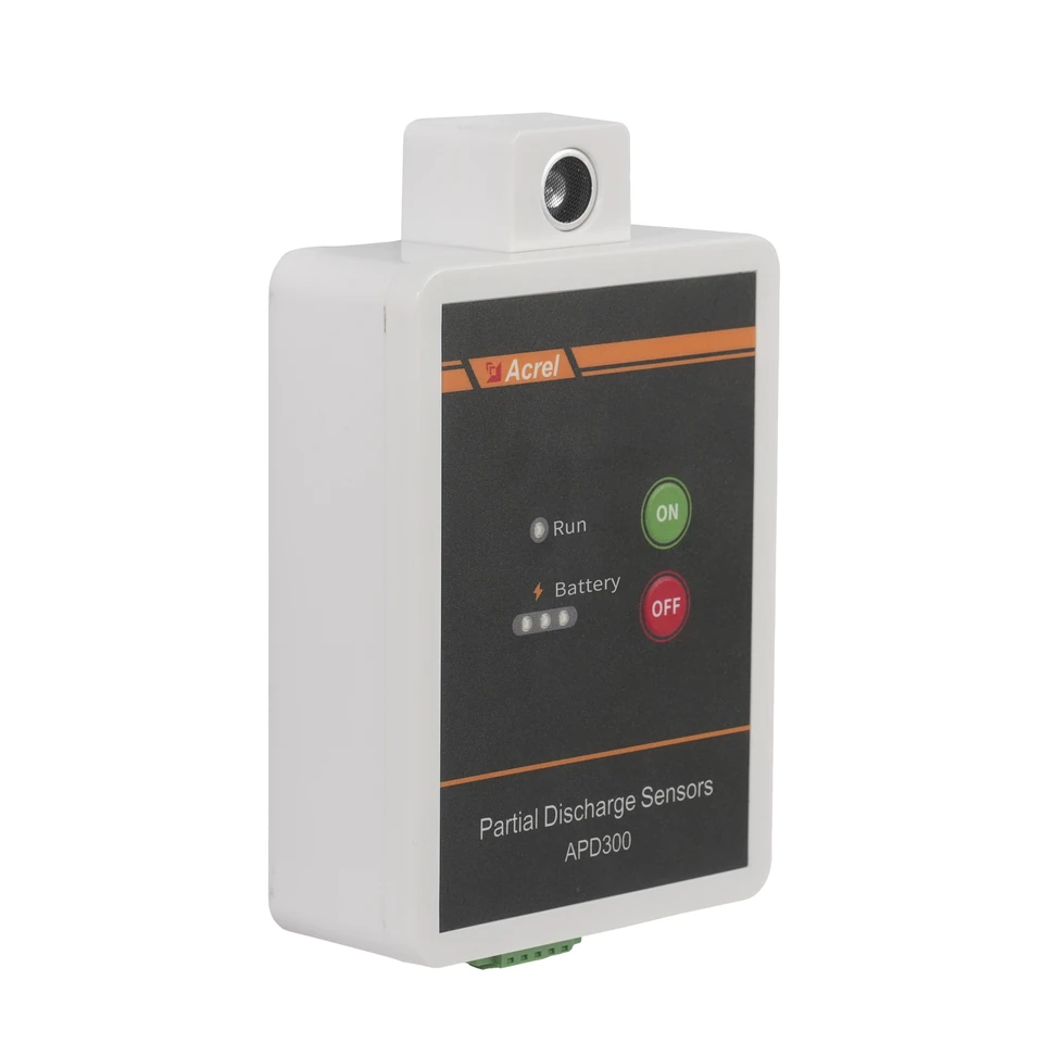
APD300-L Partial Discharge Monitoring: From Sensor Selection to Useful Trends
Build an APD300-L monitoring plan around the three sensing methods, the actual mounting position and a clear route from measurements to maintenance review.
Read guide →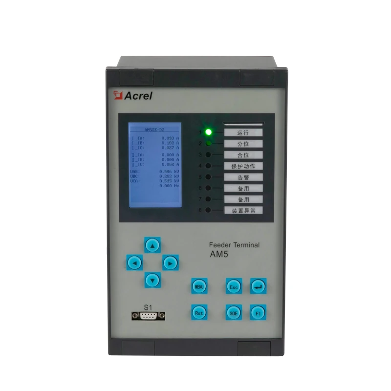
Selecting an AM5SE Protection Relay: From Application to Acceptance
Turn an AM5SE family reference into a reviewable specification: application suffix, electrical inputs, I/O allocation, communications and acceptance evidence.
Read guide →