The practical starting point
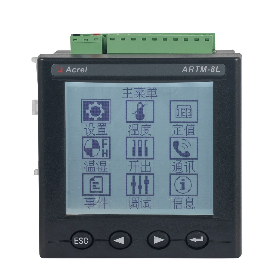
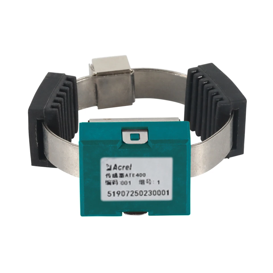
Start with the measurement point and its operating conditions. ATE400 sends temperature wirelessly and obtains its power from the conductor current; ARTM-8L receives wired sensor signals. Selecting between them means checking a complete sensor-to-monitoring path, including power, installation, compatible interfaces and the required alarm response.
- Check low-load conditions before selecting a CT-powered ATE400 sensor.
- Treat the ARTM-8L input capability and the actual probe rating as separate requirements.
- Specify receiver pairing, channel identification and alarm delivery as part of the purchase.
Compare measurement paths, not isolated instruments
A useful temperature-monitoring specification identifies the physical point, the sensor at that point, the device collecting its reading and the place where an operator sees an alarm. ATE400 and ARTM-8L occupy different positions in this chain. ATE400 is a sensor; ARTM-8L is an instrument that needs an appropriate wired input. Comparing their prices or channel counts alone would leave part of the system unspecified.
For a wireless proposal, document the sensor population, selected receiver, receiver power and onward communication. For a wired proposal, document the probe type, lead arrangement, instrument input and outputs. The comparison below is a project-planning framework; it does not establish that either arrangement is suitable for every cabinet or measurement point.
| Design question | ATE400 wireless path | ARTM-8L wired path |
|---|---|---|
| Where does measurement start? | ATE400 fixed at the selected electrical joint | A separately selected probe or supported input signal |
| What supplies the sensing path? | CT-induced power at the sensor; separate receiver supply | Instrument auxiliary supply and the selected sensor arrangement |
| What connects the point to the instrument? | A matching radio-frequency and receiver configuration | Wiring appropriate to the selected input type |
| What completes the project? | Verified reception, point mapping and onward alarms | Verified input configuration, point mapping and outputs |
Use the starting-current condition in the decision
ATE400's CT-induced power removes the battery from this model's specification, but it creates a load-related selection condition. Review the expected conductor current during the operating states in which temperature visibility is required. A sensor chosen only against the feeder's rated current may not address the project's low-load or standby expectations.
The documented starting current is therefore a screening question, not a detail to leave until commissioning. If continuous readings at very low current are essential, obtain confirmation of the proposed arrangement before ordering. Do not promise a reporting interval for operating conditions outside the documented power condition.
- ATE400Power source
- CT-induced power; starting current ≥5 AATE V2.9, PDF pp.5-6, section 1.3 ATE400 table ↗
- ATE400Sampling / transmission
- 15 s /15 sATE V2.9, PDF p.5, section 1.3 ATE400 table ↗
Select the probe before accepting the wired range
ARTM-8L supports several input families. Its maximum supported measurement range is an instrument capability, while the installed probe has its own sensing element, insulation, lead and mounting limits. The usable project range must fit the selected assembly and the instrument's applicable input specification.
The catalog includes a separate PT100 item but leaves its model field blank. That entry does not establish a probe-specific temperature range, accuracy class or insulation rating. Request the actual probe specification and confirm its lead arrangement before treating it as a complete ARTM-8L measurement channel.
| Model / parameter | Documented value & source | What it means for selection |
|---|---|---|
| ARTM-8LInput signals | Specified NTC types; three-wire PT100/PT1000; K/T/J/E/N thermocouples; 0-5 VARTM-8L T1.3, PDF p.7, Input signal rows ↗ | Identify the actual sensor type and lead arrangement before assigning the instrument input. |
| ARTM-8LPT100/PT1000 measurement range | Maximum supported -200 to +850 °C; actual range depends on the sensorARTM-8L T1.3, PDF p.8, Measurement Range ↗ | Obtain the selected probe's own specification. The instrument's maximum supported range is not a rating for the catalog's unspecified PT100 assembly. |
| ARTM-8LMeasurement channels | 8ARTM-8L T1.3, PDF p.7, section 1.2 Technical Features ↗ | Allocate each required point to a named channel and keep that mapping in the handover record. |
Values retain the original manual conditions. On a narrow screen, scroll the table sideways.
Review all supported inputs and the original instrument manual on the ARTM-8L wired temperature-monitor page.
Background reading: IEC 60751:2022 — Platinum resistance thermometers and sensors · IEC ↗
Resolve receiver pairing and physical routing
ATC600-C appears in the same catalog as ATE400. Its stated point capacity is useful for planning, but it does not establish radio coverage for a particular installed cabinet arrangement. Keep the sensor frequency, receiver configuration and intended locations together in the equipment schedule. The ATE400 distances below are open-area figures, not guaranteed cabinet-to-cabinet distances.
The receiver manual also separates compatible sensor groups. Its sharing note allows ATE210S with the listed ATE400/100/200 group only without a repeater, and excludes mixing that combination with other groups. A request for mixed sensors or repeaters therefore needs a configuration review, even when the total point count is below the receiver capacity.
- ATE400Open-area communication distance
- 150 m at 470 MHz /868-923 MHz; 50 m at 433 MHzATE V2.9, PDF p.5, section 1.3 ATE400 table ↗
- ATC600-CFunction / points
- Receiver /240 temperature pointsATC600 V1.8, PDF pp.4-5, section 1.2 ATC600-C column ↗
Background reading: Guide to Industrial Wireless Systems Deployments · NIST ↗
Define what happens after a temperature is measured
A displayed value and a delivered alarm are different acceptance items. Decide where operators need the reading, which system receives the alarm and who maintains the point-to-equipment mapping. For a wired design, the ARTM-8L's alarm and retransmission outputs may be relevant to that interface review; their presence does not automatically complete the external control circuit.
For either architecture, prepare a point list with equipment identity, measurement location, channel or sensor identity, display name and destination. Specify alarm settings through the project's equipment and operating requirements. This guide does not supply one temperature threshold for every joint, winding or cabinet.
- ARTM-8LAlarm outputs
- 5 groups normally open; AC 250 V /5 A or DC 30 V /5 AARTM-8L T1.3, PDF p.8, Alarm Output ↗
- ARTM-8LAnalogue retransmission
- 3 channels, 4-20 mAARTM-8L T1.3, PDF p.9, Transmit output ↗
- ATC600-CCommunication
- RS485; Modbus RTU; 2400 /4800 /9600 /19200 bpsATC600 V1.8, PDF p.5, Communication, Baud rate and Protocol rows ↗
A worked selection discussion
Consider a hypothetical project with electrical joints requiring monitoring and a separate group of winding-temperature probes. The joint survey records available mounting positions, operating-current conditions and receiver locations. The winding survey records the installed probe type and lead arrangement. These are two measurement requirements, even if the owner wants their values on the same supervisory screen.
The next step is to qualify each path independently: verify the ATE400 power and reception conditions for the joints, then match the winding-probe documentation to an ARTM-8L input. The integration review can subsequently define common point names and alarm destinations. This approach produces a reviewable equipment schedule without assuming that one sensing method must serve every location.
Acceptance evidence to retain
Under the project's approved commissioning procedure, record each physical point's displayed identity, the corresponding supervisory value and the intended alarm indication. Retain the approved input configuration and receiver pairing alongside the test record.
If the project also needs to evaluate an optical sensing path, continue with the ATE400 and ATC900-9 wireless-versus-fiber comparison.
Information to prepare
Use these items to turn a product discussion into a reviewable project specification.
- Measurement locations and the operating states that require temperature visibility
- ATE400 current conditions, fixing arrangement and selected frequency
- Receiver model, sensor-group compatibility and any repeater requirement
- Wired probe model, range, insulation details and lead arrangement
- Instrument and receiver auxiliary supplies and environmental conditions
- Point names, communication mapping and alarm destinations
- Approved settings and evidence required for point-by-point acceptance
Common questions
Does wireless mean that the whole monitoring system needs no power wiring?
No. ATE400 uses CT-induced power at the sensor. The receiver remains a separate device with its own supply requirements and interfaces.
Can I quote the ARTM-8L maximum range as the PT100 probe range?
No. The instrument's supported range is conditional on the sensor. The catalog's PT100 item has no model code or independent technical specification, so the selected probe needs separate confirmation.
Does receiver point capacity prove radio coverage?
No. Capacity and reception are separate checks. Match the frequency and sensor group, then verify the planned installation; open-area distance figures alone do not establish cabinet coverage.
Check the original documentation
Product specifications above link to the relevant physical PDF pages. Project examples and checklists explain how to review a configuration; final settings and acceptance criteria belong in the approved project design.
- ATE Series Wireless Temperature Sensor — Installation Instruction · V2.9 ↗Chinese / English
- ATC600 Wireless Temperature Measurement Transceiver — Operation Manual · V1.8 ↗Chinese / English
- ARTM-8L Temperature Patrol Tester — Operation Manual · T1.3 ↗Chinese / English / Russian
Explore the wider technical context
These official references provide background. Product ratings come from the selected-model manuals above; a reference does not establish product certification. Standards pages offer public summaries; full texts may require purchase.
- Guide to Industrial Wireless Systems Deployments ↗NIST
A deployment framework for defining objectives, assessing the radio environment and verifying an industrial wireless system.
- IEC 60751:2022 — Platinum resistance thermometers and sensors ↗IEC
Background on platinum resistance thermometers, sensing elements and their resistance–temperature relationship.
Related technical guides
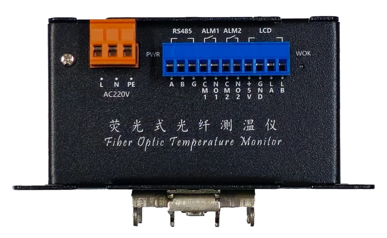
ATE400 or ATC900-9? Planning Wireless and Fiber-Optic Temperature Monitoring
Work through sensor power, fiber routing, the nine-channel kit and integration requirements before choosing a temperature-monitoring architecture.
Read guide →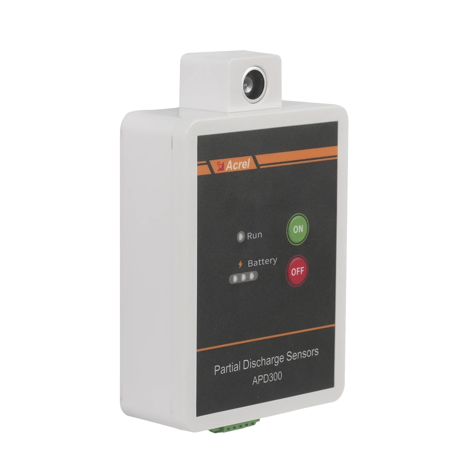
APD300-L Partial Discharge Monitoring: From Sensor Selection to Useful Trends
Build an APD300-L monitoring plan around the three sensing methods, the actual mounting position and a clear route from measurements to maintenance review.
Read guide →