The practical starting point
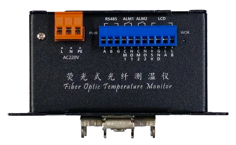
ATE400 and ATC900-9 solve the measurement-path problem differently. ATE400 uses CT-induced power and a wireless link to a matching receiver. ATC900-9 uses fluorescence fiber-optic probes connected to a powered acquisition unit. Select against the required measurement conditions and installation route, then verify the complete supplied configuration.
- Wireless planning starts with load conditions and a compatible receiver; fiber planning starts with a protected route and the required probe kit.
- The catalog selects the nine-channel ATC900-9, not the largest channel count in the wider family.
- Resolve the display and alarm-contact details before finalizing the bill of materials.
Choose the path from the measurement point
Both approaches begin with a defined physical measurement point. ATE400 is fixed at an electrical joint and transmits its reading by radio. ATC900-9 collects readings through connected fluorescence fiber-optic probes. The ATC900 manual describes applications at transformer, switchgear, cable-joint, busbar and switching-contact locations in high-voltage electromagnetic environments.
These descriptions support a comparison of architectures, not an automatic substitution. Start with drawings and a point schedule: identify where each sensing element will sit, how it will connect to the collecting device and how that device will communicate with the operator's system. A technically suitable range alone does not settle the installation design.
| Project constraint | ATE400 wireless arrangement | ATC900-9 fiber arrangement |
|---|---|---|
| Sensor power condition | Confirm conductor current supports CT-induced power | Confirm acquisition-unit supply and probe arrangement |
| Route from the point | Confirm frequency, compatible receiver and reception | Plan probe and extension-fiber routes to the unit |
| Capacity planning | Count sensors against the selected receiver configuration | Allocate the selected nine channels to named points |
| Procurement detail | List sensors, receiver and onward interfaces | List probes, extensions, adapters, display and fixing parts |
| Acceptance focus | Point identity, reception and alarm delivery | Channel identity, optical connections and alarm delivery |
For projects considering conventional sensor wiring as well, compare ATE400 wireless sensing with the ARTM-8L wired path.
Background reading: IEC 61757:2026 — Fibre optic sensors · IEC ↗
Compare the documented measurement envelopes
The models have different documented measurement ranges and accuracies. Use the expected temperature envelope and the project's measurement requirement to decide which table is relevant. Do not confuse the temperature measured by a probe with the allowable environment around the acquisition unit or receiver; both belong in the equipment review.
A displayed resolution is also a different specification from accuracy. Finer displayed increments do not, by themselves, establish a more accurate installed measurement. Keep the exact source conditions in the technical comparison and request clarification where the proposed installation introduces requirements that the supplied manual does not address.
| Model / parameter | Documented value & source | What it means for selection |
|---|---|---|
| ATE400Measurement range | -50 to +125 °CATE V2.9, PDF p.6, section 1.3 ATE400 table ↗ | Compare the expected temperature at the selected electrical joint with this model's documented measurement range. |
| ATE400Accuracy | ±1 °CATE V2.9, PDF p.6, section 1.3 ATE400 table ↗ | Keep the sensor accuracy separate from the receiver's displayed resolution and the installation review. |
| ATC900-9Measurement range | -50 to +200 °CATC900 V3.1, PDF p.2, section 4.2 Measurement parameters ↗ | Review the required probe measurement envelope separately from the acquisition unit's operating environment. |
| ATC900-9Accuracy / resolution | ±0.5 °C /0.1 °CATC900 V3.1, PDF p.2, section 4.2 Measurement parameters ↗ | Distinguish measurement accuracy from displayed increments when comparing the two proposals. |
Values retain the original manual conditions. On a narrow screen, scroll the table sideways.
Qualify the wireless operating conditions
The ATE400's power condition should be checked against the states in which the project needs a reading, including low-load operation. A matching radio configuration is another separate requirement. The frequencies in the manual are variants to specify and confirm, rather than a promise that any sensor can communicate with any receiver.
Include the receiver's supply, mounting location and onward communication in the design. ATC600-C is the catalogued receiver, with its own sensor-group and repeater restrictions. The wireless proposal should state that configuration explicitly, then identify how reception and point mapping will be demonstrated in the intended installation.
- ATE400Power source
- CT-induced power; starting current ≥5 AATE V2.9, PDF pp.5-6, section 1.3 ATE400 table ↗
- ATE400Wireless frequency variants
- 470 MHz, 433 MHz or 868-923 MHz, as listed for ATE400ATE V2.9, PDF p.5, section 1.3 ATE400 table ↗
- ATC600-CFunction / points
- Receiver /240 temperature pointsATC600 V1.8, PDF pp.4-5, section 1.2 ATC600-C column ↗
Background reading: Guide to Industrial Wireless Systems Deployments · NIST ↗
Make the fiber route part of the design
A fiber arrangement requires a route from every probe to the acquisition unit. Review bends, connection locations, protection against crushing and access for later inspection on the cabinet drawing. The ATC900 safety guidance specifically requires clean optical interfaces, protective caps when disconnected, and avoidance of small-radius bends and trampling. Those requirements belong in the installation plan, rather than being left to the final assembly stage.
The probe withstand entry is a test condition with a stated length, voltage and duration. It does not establish a general system-voltage certification or settle the clearances of an assembled cabinet. Keep the original condition attached to the value and have the complete installation assessed against the project's requirements.
- ATC900-9Minimum fiber bend radius
- 25 mmATC900 V3.1, PDF p.2, safety guidance and section 4.3 ↗
- ATC900-9Probe withstand condition
- 20 cm at 80 kV, 1 minATC900 V3.1, PDF p.2, section 4.3 Fiber-optic probe parameters ↗
Reconcile the kit and interfaces before ordering
Appendix 2 identifies the ATC900-9 kit, including its acquisition unit, LCD display, probes, extension fibers, adapters and fixing parts. Compare the proposed route against the actual kit schedule. The catalog's separate 1.2 m fluorescent-fiber probe entry does not identify an independently documented interchangeable probe model; confirm the supplied probe and connector arrangement as part of the order.
Two source details need explicit resolution. The overview calls the HMI optional, while the ATC900-9 kit lists an LCD display. The AC alarm-contact voltage differs between the electrical-parameter section and the communication appendix. Ask the supplier to confirm the delivered display and contact rating in the final configuration rather than selecting one conflicting value silently.
- ATC900-9Selected configuration
- ATC900-9: 9 temperature channelsATC900 V3.1, PDF p.11, Appendix 2 ATC900-9 kit; PDF p.2 channel options ↗
- ATC900-9Communication
- RS485, Modbus RTU; default 19200 bps, adjustableATC900 V3.1, PDF p.12, Appendix 3 Communication mode ↗
- ATC900-9Over-temperature outputs
- 2 relay dry-contact outputs; contact voltage rating requires clarificationATC900 V3.1, PDF p.4 rear-panel terminals; PDF pp.2,12 contain differing voltage ratings ↗
Check the selected channel configuration, kit notes and unresolved source differences on the ATC900-9 fiber-optic temperature-monitor page.
Turn the comparison into an acceptance plan
In a hypothetical nine-point cabinet project, first map every required location to a named channel. For an ATC900-9 proposal, review whether the supplied probe and extension arrangement reaches each point while meeting the routing constraints. For an ATE400 proposal, review the same points for current conditions, fixing suitability and the selected receiver arrangement. Neither proposal passes simply because its brochure shows enough points.
The acceptance plan should then connect the physical point to its local indication, supervisory value and intended alarm destination. Record the installed model, channel mapping, communication configuration and approved settings. Use the manufacturer's procedures within the project's approved commissioning process; the comparison here is a planning aid, not a substitute for an installation or electrical-work procedure.
A useful handover package
Retain the as-installed point schedule, route drawings, confirmed kit list, interface settings and acceptance records together. This gives the maintenance team a way to identify the intended sensor or probe when a channel needs investigation.
Information to prepare
Use these items to turn a product discussion into a reviewable project specification.
- Named measurement points and the temperature envelope required at each
- ATE400 operating-current conditions and confirmed radio configuration
- ATC900-9 channel allocation and acquisition-unit environment
- Probe lengths, extension routes, adapters and minimum bend-radius review
- Confirmed kit contents, including display and fixing parts
- Written clarification of the ATC900 AC alarm-contact rating
- Supervisory mapping, approved alarm settings and acceptance records
Common questions
Does the ATC900 family maximum make this a twelve-channel unit?
No. The catalog selects ATC900-9. Its channel allocation and equipment schedule must use that nine-channel configuration.
Does the stated probe withstand test certify the entire switchgear assembly?
No. The entry retains its stated length, voltage and duration. It is not a cabinet-level certification or a replacement for the project's installation assessment.
Is the catalog's separate fluorescent probe automatically a confirmed replacement?
No. Its catalog identity and length alone do not establish full interchangeability. Confirm the actual probe, connector and supplied configuration against the selected equipment documentation.
Which approach is always better?
Neither is selected by that question alone. Evaluate measurement requirements, current conditions, physical routing, receiver or acquisition-unit interfaces, and the evidence needed at acceptance.
Check the original documentation
Product specifications above link to the relevant physical PDF pages. Project examples and checklists explain how to review a configuration; final settings and acceptance criteria belong in the approved project design.
Explore the wider technical context
These official references provide background. Product ratings come from the selected-model manuals above; a reference does not establish product certification. Standards pages offer public summaries; full texts may require purchase.
- IEC 61757:2026 — Fibre optic sensors ↗IEC
A general framework for characterizing fibre-optic sensors and their components.
- Guide to Industrial Wireless Systems Deployments ↗NIST
A deployment framework for defining objectives, assessing the radio environment and verifying an industrial wireless system.
Related technical guides
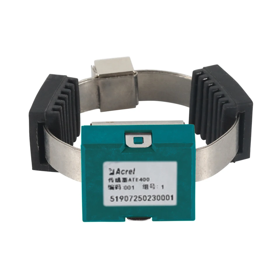
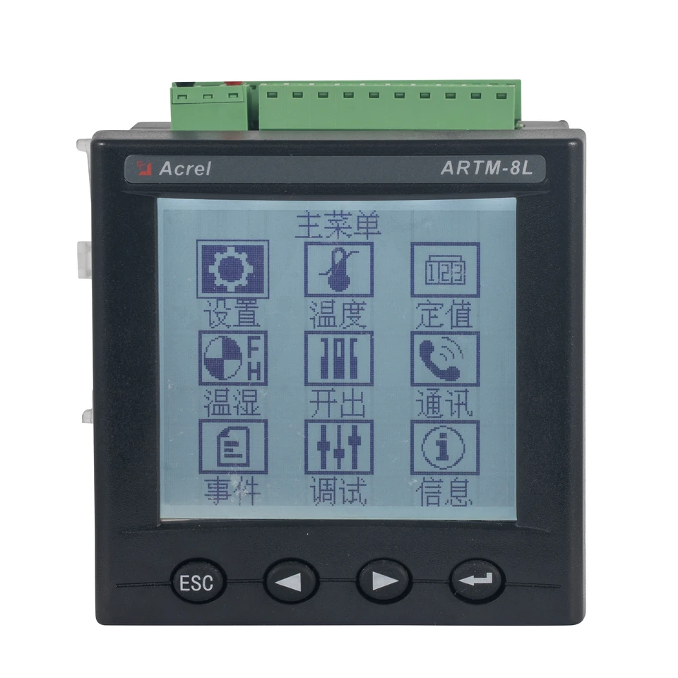
Wireless or Wired Temperature Monitoring? ATE400 and ARTM-8L Selection Guide
Compare the complete measurement paths, from sensor power and probe selection to receiver capacity, alarm outputs and acceptance checks.
Read guide →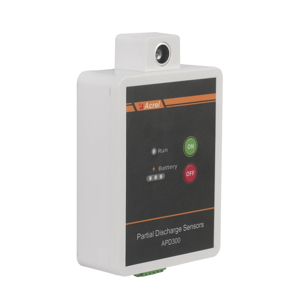
APD300-L Partial Discharge Monitoring: From Sensor Selection to Useful Trends
Build an APD300-L monitoring plan around the three sensing methods, the actual mounting position and a clear route from measurements to maintenance review.
Read guide →